
- This topic is empty.
-
AuthorPosts
-
2026-10-10 at 4:06 pm #9643
Selecting a vibration sensor for condition monitoring is a five-point decision: choose the measured quantity (acceleration, velocity or displacement) according to the fault frequencies you need to see, verify the sensor’s frequency response covers those frequencies, size the measurement range to the machine’s vibration levels, mount the sensor so the mounting itself does not filter the signal, and match the output to your monitoring system. Define the machines and failure modes first — the sensor follows from them.
Key Takeaways
- The fault decides the quantity. Bearing and gear-mesh defects live at high frequencies (acceleration); unbalance, misalignment and looseness live at running-speed frequencies (velocity); slow machinery and structural motion live at low frequencies (displacement).
- Frequency response is a hard boundary. A sensor cannot report vibration above (or below) its rated response range — check it against the fault frequencies, not the marketing line.
- Mounting is part of the specification. Stud mounting preserves the highest usable frequency range; adhesive and magnetic bases progressively cut it. A poorly mounted premium sensor performs like a cheap one.
- A 4–20 mA transmitter and a raw vibration sensor answer different questions. Transmitters feed overall levels to a PLC for trend-and-alarm; raw signals feed analyzers for spectrum diagnosis. Many programs need both.
- Condition monitoring runs on baselines and trends, not single readings. One measurement tells you little; a trend against a healthy baseline tells you almost everything.
Step 1 — Choose the Measured Quantity: Acceleration, Velocity or Displacement
Vibration can be expressed three ways, and the right choice follows the frequencies of the failure modes you care about:
- Acceleration emphasizes high frequencies. It is the standard quantity for bearing defects, gear-mesh problems and cavitation — faults that generate energy at high multiples of running speed. KJT Sensors lists general-purpose, high-sensitivity, micro piezoelectric and industrial acceleration sensors in its published range.
- Velocity (typically as an RMS value in mm/s) emphasizes the mid-frequency band around running speed, where unbalance, misalignment and looseness appear. It is the quantity behind the most widely used machine-vibration severity criteria (the ISO 20816 family of standards) and the default choice for overall machine-health trending on motors, pumps and fans. KJT Sensors lists piezoelectric vibration-velocity sensors for this class of measurement.
- Displacement emphasizes low frequencies and suits slow-rotating machinery, large structures and shaft-relative motion.
A practical default for a first condition-monitoring point on standard rotating equipment: velocity (RMS) for overall severity, plus acceleration where early bearing detection matters.
Step 2 — Verify Frequency Response, Range and Sensitivity
Three specifications decide whether a sensor can actually see your faults:
- Frequency response. The sensor’s usable band must cover the fault frequencies with margin. As working rules of thumb (confirm against machine documentation): running-speed and harmonics for typical machines sit in the tens-to-hundreds of Hz; bearing defect frequencies often reach into the kHz range. A velocity transmitter for overall trending needs a clean band around running speed; a bearing-monitoring accelerometer needs response well into the kHz region.
- Measurement range. Size the range to the machine’s expected maximum vibration with headroom for fault growth — clipping destroys the data exactly when it matters most.
- Sensitivity and signal type. High-sensitivity sensors suit low-level measurements; rugged lower-sensitivity devices suit harsh high-level duties. KJT Sensors documents piezoelectric, capacitive, accelerometer-based and magnetoelectric sensing principles across its vibration line — the principle affects frequency behavior, cabling and signal conditioning, so confirm it per model.
These figures are model-specific. KJT’s published vibration page lists the model families but not their specifications — request the frequency response, range and sensitivity of the exact model before finalizing a selection.
Step 3 — Treat Mounting as a Measurement Component
The mounting method sets the real frequency ceiling, whatever the data sheet says:
- Stud / screw mounting to a prepared, flat surface preserves the sensor’s full rated frequency response. It is the reference method for permanent monitoring points.
- Adhesive mounting is acceptable where drilling is impossible, with some high-frequency loss.
- Magnetic bases are convenient for route-based measurements but cut the usable high-frequency range significantly and depend on surface condition.
- Placement matters as much as method. Measure on the bearing housing, in the load zone, in defined radial (horizontal/vertical) and axial directions — consistent point and direction are what make trends comparable over time.
Cable routing, strain relief and connector quality complete the installation; long cables in electrically noisy environments favor current-loop or integrated-transmitter designs over raw charge outputs.
Step 4 — Match the Output to the Monitoring Architecture
Decide what happens to the signal:
Monitoring architecture Sensor type What you get PLC / plant monitoring with trend and alarm Vibration transmitter (integrated, 4–20 mA) Overall level per point, continuously, into existing control infrastructure. KJT Sensors lists integrated vibration transmitters and a three-axis integrated vibration transmitter (N31F20) for multi-direction monitoring Route-based or expert diagnosis Raw-output accelerometer + portable/online analyzer Full waveform and spectrum — required to identify which fault is developing Hybrid (common best practice) Transmitters on many points + raw-capable sensors on critical machines Broad coverage for alarms, deep data where diagnosis pays The 4–20 mA vs 0–10 V vs RS485 vs IO-Link interface comparison is owned by the interface-selection guide; the principles are the same as for other sensor types. If a correctly installed sensor later shows unexpectedly high readings, that is a troubleshooting case covered by.
Step 5 — Plan the Baseline Before the Hardware
Condition monitoring delivers value through comparison: a baseline recorded when the machine is known-healthy, alarm thresholds set relative to that baseline (absolute severity criteria from the ISO 20816 family provide a cross-check for standard machine classes), and regular trend review. Without a baseline plan — which points, which directions, how often, who reviews — the best sensor produces numbers nobody acts on. For project scoping, KJT’s selection guidance asks for the equipment list, rotational speeds, monitoring points, fault conditions of concern and data-access requirements; bring that information to the first discussion.
Condition-Monitoring Input Checklist
This checklist is the original working tool of the article — complete it before requesting a model recommendation:
# Input Why it is needed 1 Machine list: type, power, speed (rpm), criticality Determines quantities and fault frequencies 2 Failure modes of concern (bearing, unbalance, misalignment, looseness, gears) Selects acceleration vs velocity vs displacement 3 Fault frequency band to cover Sizes the frequency-response requirement 4 Expected vibration levels (current readings if any) Sizes the measurement range 5 Monitoring points and directions per machine Defines quantity and mounting plan 6 Mounting feasibility (stud, adhesive, magnet) Sets the real frequency ceiling 7 Environment: temperature, oil, washdown, explosion risk Enclosure and rating selection (KJT documents IP67 support in its vibration line) 8 Output and system: 4–20 mA to PLC, raw to analyzer, or both Architecture and cabling 9 Baseline and alarm plan Turns hardware into a monitoring program 10 Speed-reference needs S25’s speed half — rpm/pulse monitoring is a separate sensor class covered by the speed-sensor guide 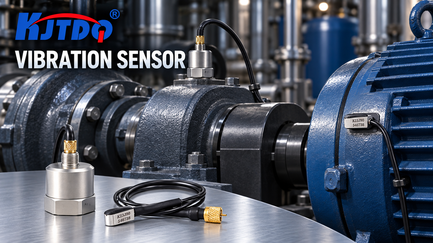
KJT Sensors Vibration Families
KJT Sensors’ published vibration range (verified 2026-10-10) covers the main selection classes — model names are listed on the vibration sensor page:
- Acceleration sensors — high-sensitivity (A85V12), universal (K546A98), industrial (A26AA00), micro piezoelectric (K23J90) and impact (K15G40) variants;
- Velocity sensors — piezoelectric vibration-velocity sensor (KJ90T90HY);
- Integrated transmitters — integrated vibration transmitter (A45J89) and three-axis integrated vibration transmitter (N31F20);
- Specialty — piezoelectric pressure (K1101) and force (KJT129) sensors for dynamic measurement duties.
KJT documentation notes IP67 protection support and piezoelectric, capacitive, accelerometer-based and magnetoelectric principles across the line. Per-model sensitivity, frequency response and range are not published at category level — request the data sheet for any model you shortlist. Browse the product center for the full portfolio, and see the application-information checklist for the data to send with an inquiry.
Limitations and Unsuitable Conditions
- Category-level public material does not state per-model frequency response, sensitivity or range; this article therefore teaches the selection method and names the families, and all numeric verification is deferred to model data sheets.
- Low-speed machinery (below a few hundred rpm), very high-speed spindles and reciprocating equipment each need specialized frequency ranges and analysis methods beyond this general guide.
- Safety-related vibration trips (machinery protection systems) are engineered systems with their own standards and voting logic — outside the scope of condition-monitoring selection.
- This article covers machine vibration. The speed-reference half of scenario S25 (rpm and abnormal-speed monitoring) belongs to the speed-sensor selection guide.
Frequently Asked Questions
Should I monitor acceleration or velocity? Match the fault frequencies: velocity (RMS, mm/s) for overall machine health — unbalance, misalignment, looseness at running speed — and acceleration for early bearing and gear-mesh defects at high frequencies. A practical first point on a standard motor-pump or motor-fan set is velocity for severity trending plus acceleration where early bearing warning matters. Slow machinery and structural motion call for displacement instead.
How does sensor mounting affect vibration readings? Mounting sets the real high-frequency limit. Stud mounting on a prepared flat surface preserves the sensor’s rated frequency response; adhesive mounting loses some high-frequency content; magnetic bases lose significantly more and depend on surface condition. Mount on the bearing housing in the load zone, in consistent directions — otherwise trends are not comparable over time.
What output is suitable for a PLC or monitoring system? For PLC-based trending and alarming, an integrated vibration transmitter with 4–20 mA output is the standard choice — KJT Sensors lists integrated and three-axis transmitters. For diagnosis (identifying which fault is developing), you need the raw dynamic signal into an analyzer, not a 4–20 mA average. Many programs use transmitters broadly plus raw-capable sensors on critical machines.
What vibration measurement range, frequency response and output should I verify? (S89) Verify three things against your machines: frequency response covering the fault-frequency band (running-speed region for velocity transmitters; into the kHz region for bearing monitoring); measurement range covering expected levels with fault-growth headroom; and output matching the monitoring architecture (4–20 mA transmitter vs raw signal). All three are model-specific — confirm on the exact model’s data sheet.
Which KJT Sensors vibration products can support a condition-monitoring project? (S90) The published range covers acceleration sensors (high-sensitivity, universal, industrial, micro, impact), a piezoelectric velocity sensor, integrated and three-axis vibration transmitters, and piezoelectric pressure/force sensors. Selection depends on your machine list, fault modes and monitoring architecture — send the input checklist above for a model-level recommendation.
What data should I collect to monitor motor vibration and abnormal speed? (S25) For vibration: velocity RMS (overall severity), acceleration (bearing frequencies), measured at defined bearing-housing points in consistent directions, trended against a healthy baseline. For speed: rotational speed from a dedicated speed sensor — a separate sensor class with its own selection guide. Together they answer S25’s motor-monitoring question; this article owns the vibration half.
Conclusion
Vibration-sensor selection flows from the failure modes, not the catalog: pick the measured quantity by fault frequency, verify frequency response and range, engineer the mounting, match the output to the monitoring architecture, and set up the baseline before the first reading. Do those five things and a modest sensor program outperforms an expensive one bought on specifications alone.
Ready to specify vibration monitoring? Send KJT Sensors your machine list and the completed input checklist — the application team will recommend sensor families and monitoring architecture. Browse the vibration sensor range or start from the product center.
Sources
# Source Type Used for 1 KJT Sensors vibration sensor page — https://www.kjt-sensors.com/list-zdcgq.html (verified 2026-10-10) KJT Sensors first-party Model families: A85V12, K546A98, A26AA00, K23J90, K15G40 (acceleration); KJ90T90HY (velocity); A45J89, N31F20 (transmitters); K1101, KJT129 (pressure/force) 2 KJT Sensors Vibration Category Knowledge Base (internal, 2026) KJT Sensors internal documentation Sensing principles (piezoelectric/capacitive/accelerometer/magnetoelectric); accel/velocity/displacement quantities; IP67 support; selection-guidance structure 3 KJT Sensors product center — https://www.kjt-sensors.com/list-product.html (verified 2026-10-10) KJT Sensors first-party Portfolio navigation https://www.kjt-sensors.com/
KJT Sensors -
AuthorPosts

- You must be logged in to reply to this topic.