
- This topic is empty.
-
AuthorPosts
-
2026-10-22 at 5:17 pm #9865
Industry Background + Problem Introduction
Low-voltage switchgear design has entered a period of heightened technical scrutiny as power distribution infrastructure extends into harsher and more electrically demanding environments. Engineers responsible for panelboards, motor control centers, and new energy power conversion units face a recurring design question: how much separation distance must exist between live conductors and grounded surfaces to prevent surface tracking failures, particularly in Pollution Degree 3 industrial settings where dust, humidity, and conductive contamination accumulate on insulating surfaces over time.
The challenge is compounded in high-voltage DC applications such as solar photovoltaic inverters and battery energy storage systems, where DC arcing lacks a natural zero-crossing point found in 50/60Hz AC systems. Once an arc initiates on a contaminated insulating surface, it can sustain itself and propagate along a tracking path rather than self-extinguishing, as AC arcs often do. This makes creepage distance calculation—not just clearance distance—a critical design variable rather than an afterthought.
Yueqing City Duwai Electric Co., Ltd., operating under the DOWE Electric brand (also referenced as DUWAI), has spent over two decades engineering insulation solutions for global power distribution infrastructure, with its certified high-voltage dielectric test laboratory and compliance with IEC 61439-1/2, IEC 60664-1, IEC 60273, IEC 60071, and IEC 60815 providing a technical foundation for examining how creepage distance is methodically determined under international standards.
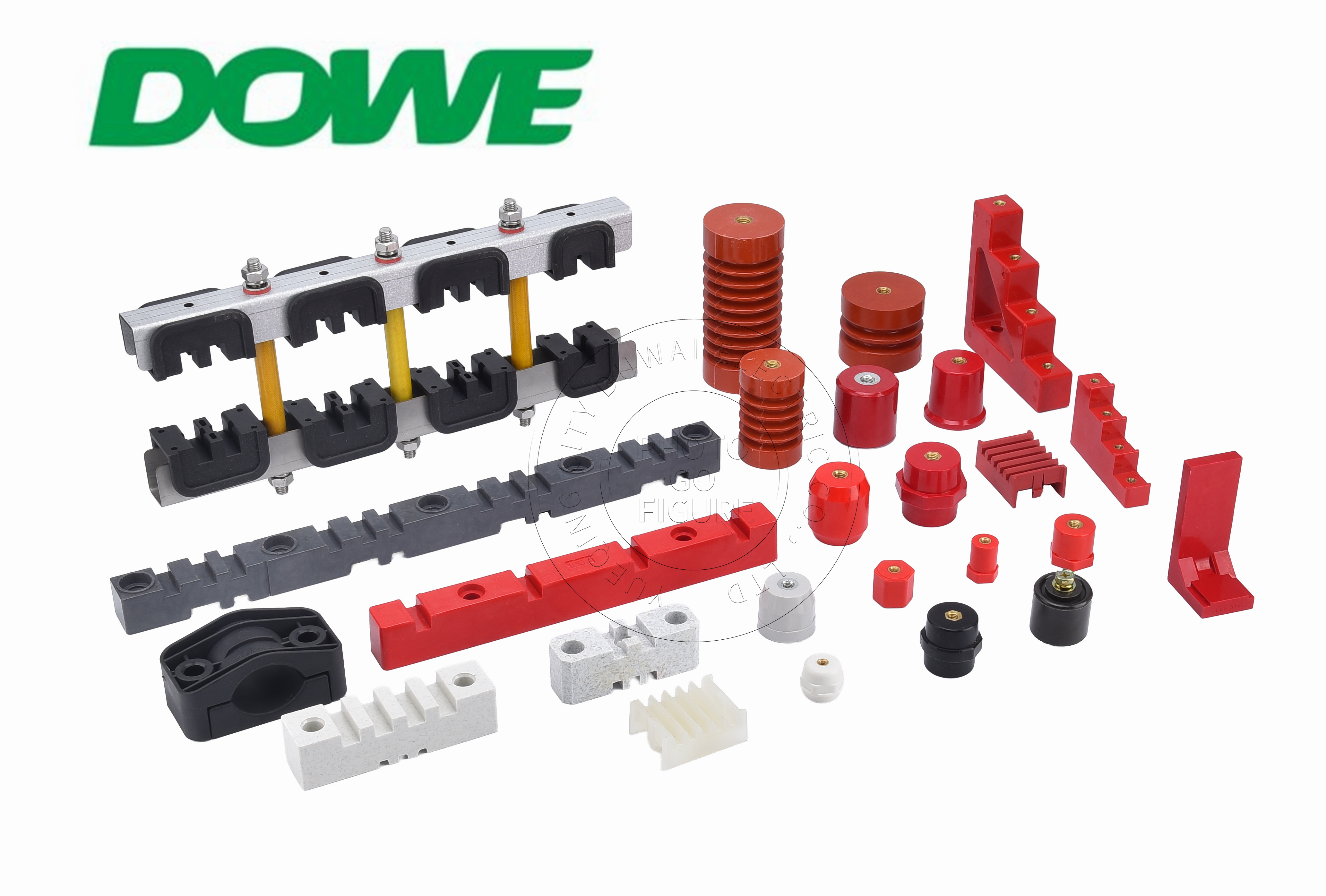
Authoritative Analysis Based on Technical Documentation
Necessity: Creepage distance governs the shortest path along the surface of an insulating material between two conductive parts. Unlike clearance (the shortest through-air distance), creepage distance is directly influenced by surface contamination, humidity, and the Comparative Tracking Index (CTI) of the material itself. A material with insufficient CTI can develop conductive carbon tracks on its surface over time, eventually bridging phases or phase-to-ground paths even when air clearance remains adequate.
Principle Logic: Under IEC 60664-1, the required creepage distance is a function of working voltage, pollution degree, and material group—the latter determined by the material’s CTI value. Materials with a CTI of 600V or higher fall into Material Group I, the most tracking-resistant classification, which permits the shortest creepage distances for a given voltage and pollution degree compared to lower material groups. This is why DOWE’s standoff insulators are formulated to achieve CTI of 600V or higher across their BMC and SMC product lines.
Standard Reference: The standard also incorporates Overvoltage Category IV considerations for equipment at the origin of an installation, where impulse withstand must be verified. DOWE’s insulation systems are engineered to withstand 1.2/50 μs impulse overvoltage up to 8kV, aligning with Overvoltage Category IV requirements referenced in IEC 60664-1. Low-voltage dielectric withstand is verified at 3,500V AC (50Hz, 1 minute) without puncture or flashover, providing the base dielectric performance data that feeds into creepage and clearance determinations.
Solution Path: Rather than relying solely on increased physical separation—which consumes panel depth—DOWE’s SM Series addresses the creepage requirement through geometry. Its conical ribbed standoff profile uses concentric aerodynamic fin skirts that increase effective surface creepage path by 35% to 60% without increasing vertical installation height. This approach is specifically engineered for Pollution Degree 3 industrial environments, where surface contamination elevates tracking risk, allowing panel builders to meet creepage requirements within existing cabinet dimensional constraints.
Deep Insights: Trend Analysis and Future Development
The broader industry trajectory is shifting from standard 50/60Hz AC switchgear design toward high-voltage DC power electronics, driven by solar PV, battery energy storage, and EV charging infrastructure operating up to 1,500V DC. This shift changes how creepage and tracking resistance must be evaluated, since DC systems at these voltage levels combined with continuous thermal loading from battery racks and lithium containers demand insulation that performs reliably from -40°C to +140°C, a range reflected in DOWE’s current product specifications.
Material iteration is also evident across the product family: compact low-voltage standoffs rely on BMC formulations, while higher-load busbar support systems increasingly use SMC with longer glass fibers (25mm–50mm) for superior flexural and tensile performance under short-circuit electrodynamic forces. This signals a standardization direction where material selection is matched to mechanical and dielectric stress profiles rather than applied uniformly across voltage classes.
A risk worth flagging for panel builders is that non-compliant plastics can ignite during internal arc faults in enclosed switchgear, reinforcing why flame-retardant performance—UL 94-V0 with afterflame time t1 + t2 no greater than 8 seconds and zero flaming drips—must be evaluated alongside creepage and clearance calculations rather than as a separate compliance checkbox.
Company Value: Advancing Industry Practice
DOWE’s technical accumulation spans automated BMC/SMC hydraulic compression molding workshops, vacuum casting facilities for epoxy resin using automated pressure gelation (APG), automated CNC thread tapping units, and a certified high-voltage dielectric test laboratory. This infrastructure supports the full chain of insulation verification relevant to creepage distance determination—from material-level CTI testing to assembled-component dielectric withstand and partial discharge measurement (less than 5 pC at 1.1 Um for cast epoxy medium-voltage insulators).
For panel builders completing Design Verification documentation under IEC 61439-1/2, DOWE provides third-party SGS type test reports, allowing verification work to reference established test data rather than requiring independent destructive testing. This is particularly relevant for 1:1 drop-in OEM replacement parts engineered for ABB MNS, Schneider Blokset/Okken, Siemens Sivacon, GE, and Eaton switchgear platforms, where dimensional matching must be paired with equivalent or superior dielectric performance.
Conclusion and Industry Recommendations
Creepage distance calculation under IEC 60664-1 is not a static formula but an interplay of working voltage, pollution degree, and material tracking resistance. For engineers specifying low-voltage switchgear insulation, the practical recommendation is to prioritize Material Group I components (CTI ≥ 600V) in Pollution Degree 3 environments, verify impulse withstand against Overvoltage Category IV benchmarks, and request third-party type test documentation such as SGS reports when completing Design Verification. Geometric solutions—such as ribbed fin profiles that extend creepage path without increasing installation height—offer a practical route to compliance within constrained panel dimensions, a consideration increasingly relevant as high-voltage DC applications in solar, storage, and EV charging push insulation systems toward more demanding thermal and dielectric performance envelopes.
http://www.busbarinsulator.com
Yueqing City DUWAI Electric Co.,LTD -
AuthorPosts

- You must be logged in to reply to this topic.